What
CNC (=computerized numerical control) milling is the process of removing material by using a rotary cutter that is positioned by a computer. The advantage of CNC milling over cutting matarial by hand is that it is far more accurate, reproducable and in many cases a lot faster. I have been constructing my own CNC milling machines and after many attemps with various levels of success, I switched to a commercial mechanics kit that I then modified for my purposes. I hope to share my experiences and make your CNC machine build easier.
When
For some time home-made CNC mills and later 3D printers were all over internet pages about DIY projects and electronics. The topic caught my attention early on, but there were no affordable commercial solutions or kits available. I found various designs on the internet. They were mostly made of wood and required a high-level of wood working skills and tools, but I decided to try, learn and see how far I could get. The process took a couple of years and in the end I moved to a pre-built mechanics kit. The time was not lost though, as I already owned many of the requires parts and knew exactly what to look out for in shopping for the mechanics kit.
Background
My starting point and first motor driver was a custom board using a combination of an L297 stepper motor controller and an L298 motor driver for each of the 3 axis of the machine (X, Y and Z). The electronics were powered by a standard ATX power supply from a computer. The driver boards were etched (see my other post on the topic). I quickly realized that the components would run very hot and I had to cool them by adding copper tubing.
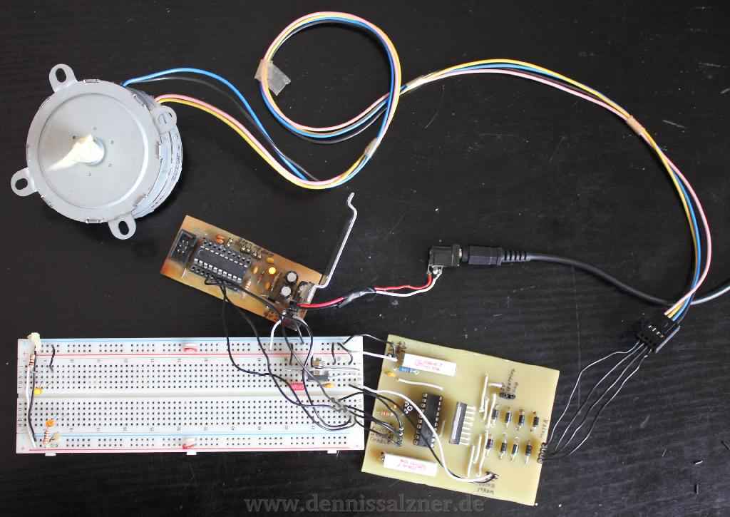
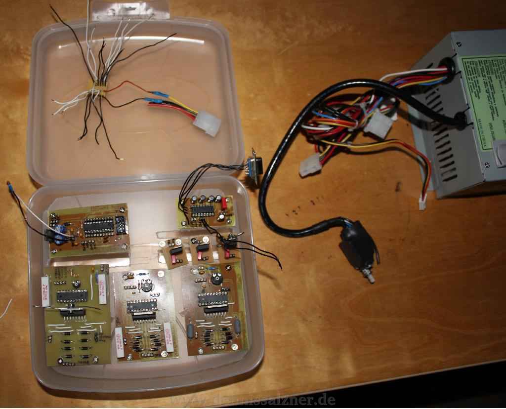
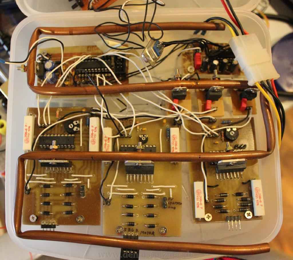
There were many issues with the electronics and my PCB etching process did not work well at the time. I had troubles getting all three driver boards to work at the same time, but learned a lot during the process.
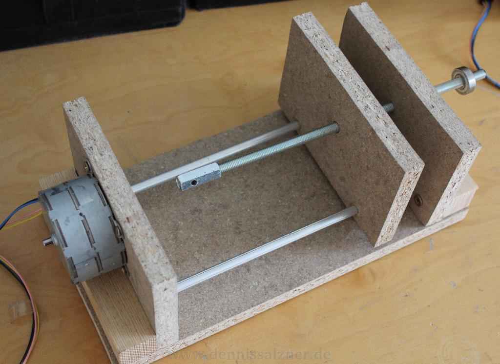
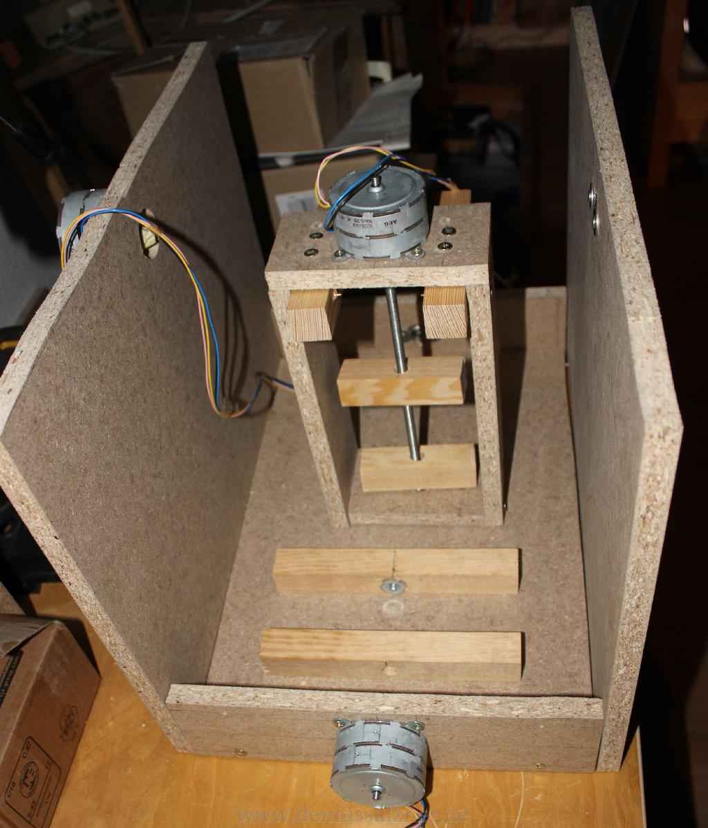
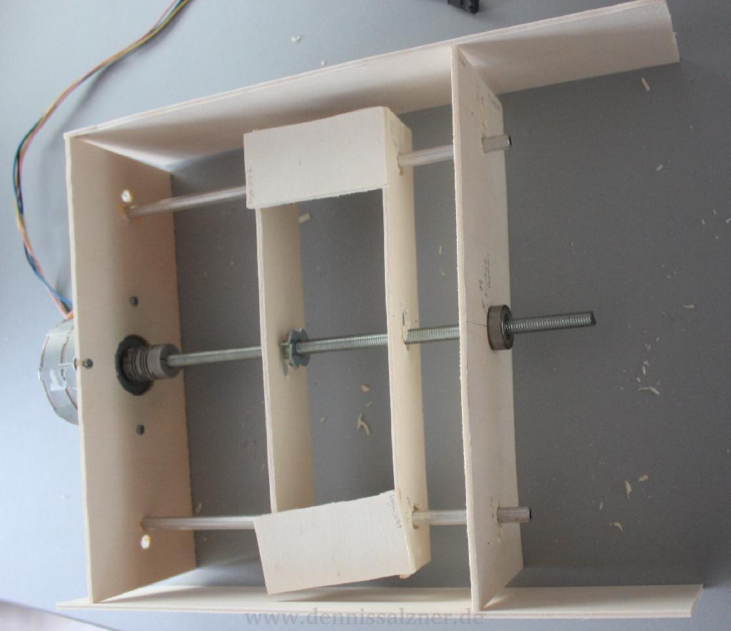
I started constructing the frame of the CNC mill nevertheless in order to run some first tests. The z-axis did work, but the building-supplies-store-grade threaded rod had too many threads per length and thus the motor needed far too many rotations to cover even the most minute distance. Apart from that the wood was too heavy, the threaded rod of too poor quality and so the very weak and cheap motor would get stuck. This did teach me some important lessons, though: A good cnc mill requires a high quality threaded rod with a low number of theads per length or belt driven mecahnics, powerful motors, an accurate but light-weight frame and realiable motor drivers.
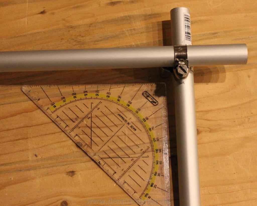
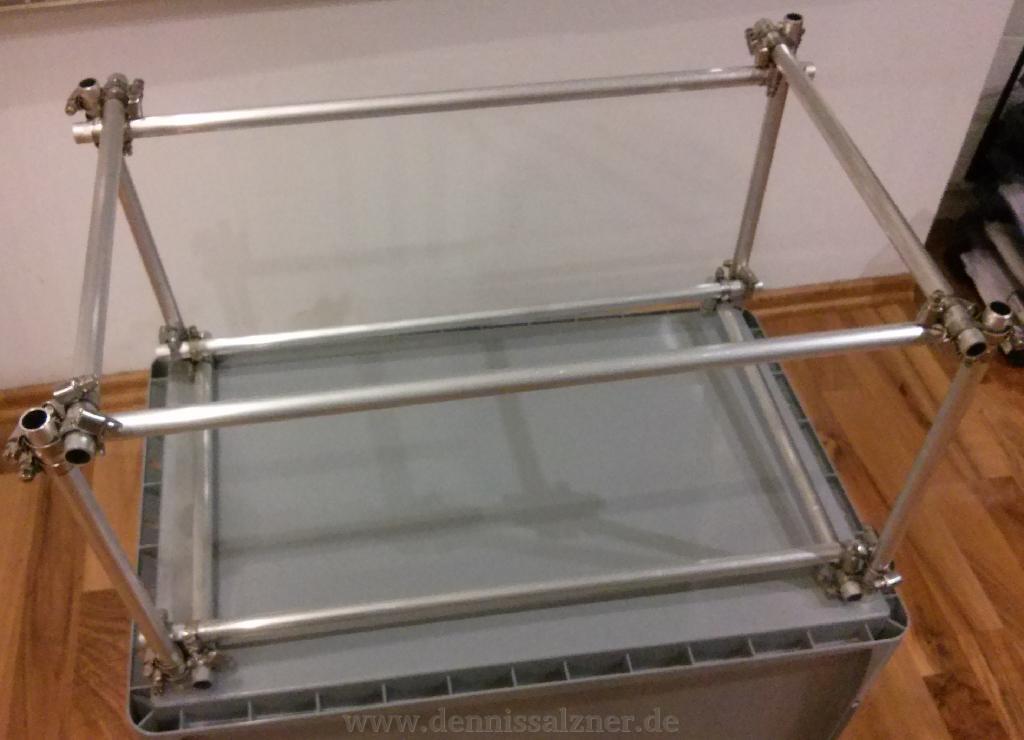
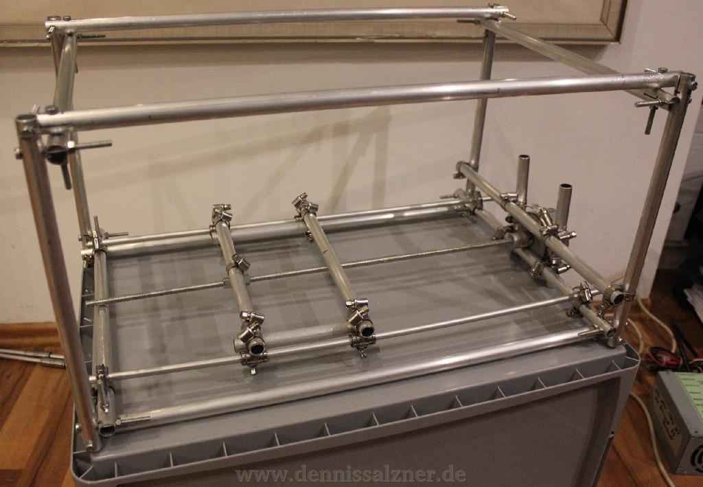
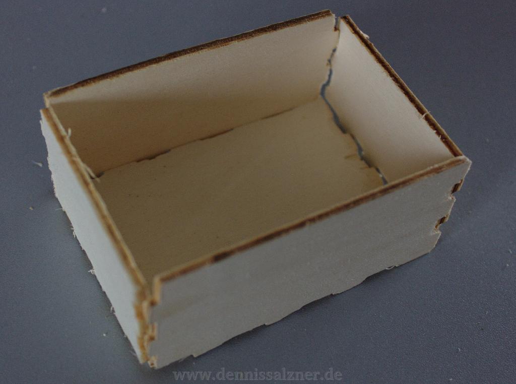
After the failed attempts I started with more lightweight prototyp builds. A very lightweight plywood construction for tests only and then frames built from aluminium. I found that aluminium tubes are very easy to cut accurately using a pipe cutter. Hoseclamps can be tightend to the tubing in such a way that 90 degree angles can be constructed with reasonable accuracy. A linear ball bearing can travel on aluminium tubes. The concept of aluminium tubes might have worked if I had given up on the poor quality threaded rod and used a belt drive. Too much weight on the long X axis in the bottom caused the tube to bend. The actual working area was also too small in this design to be anywhere near useful. The lessons from this are: Use belt drive instead of threaded rod, use thicker aluminium tubes and larger linear ball bearings for the axis and plan for a decent size working area.
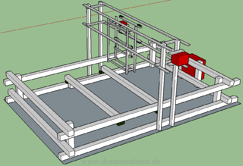
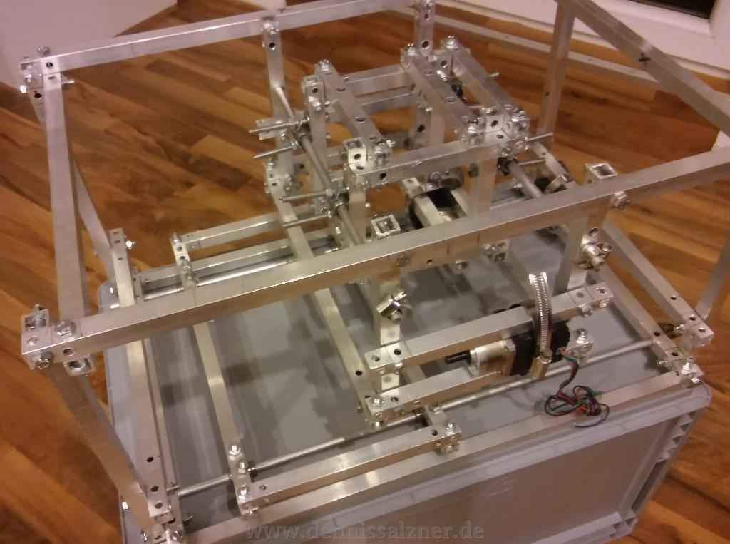
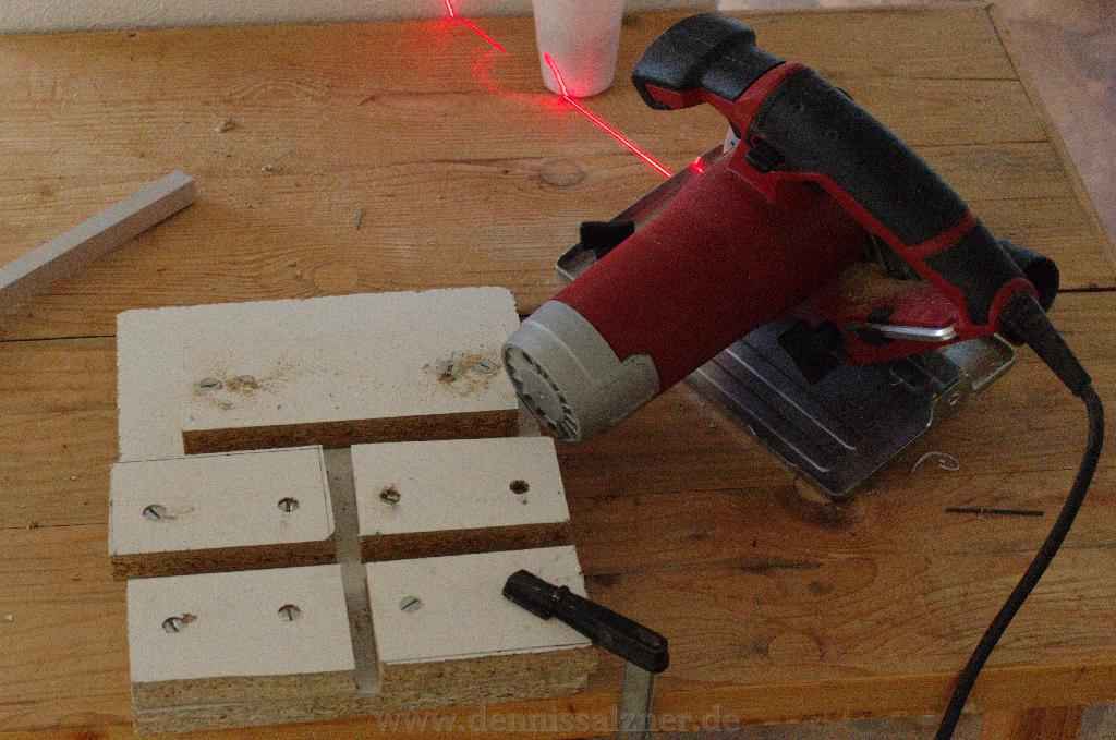
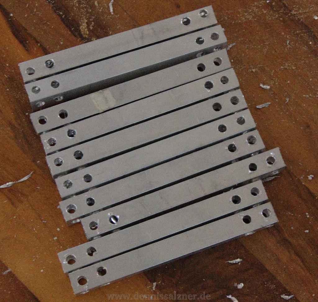
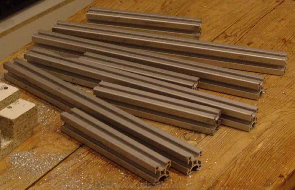
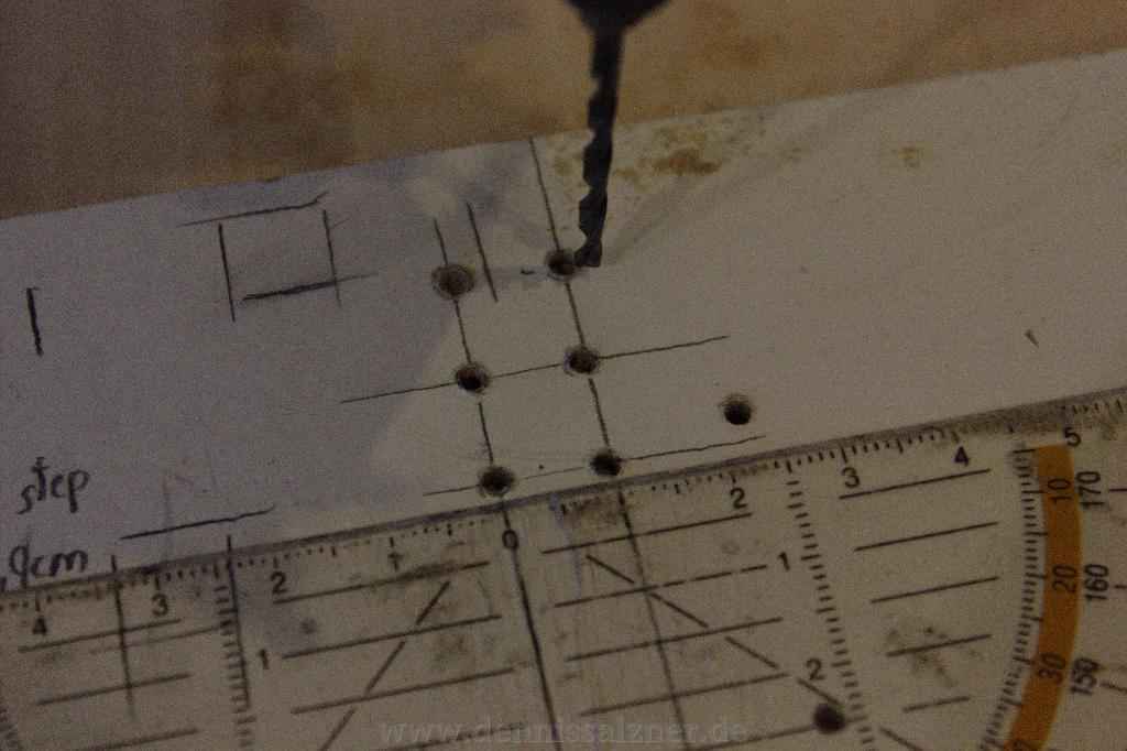
From there I moved on to square aluminium pipes and started with a CAD drawing. Building the mill from square aluminium pipes made the build substantially more difficult. It was far harder to achieve an accurate construction. Now I couldn’t use a pipe cutter, but had to build a custom rig for my circular saw. I also needed a special paper cap (not in the photos) in order to acurrately drill holes in the square aluminium pipes. Of course this can be done with proper tools, a chop saw and drill press, but I didn’t have these tools at the time and didn’t want to spend the money.
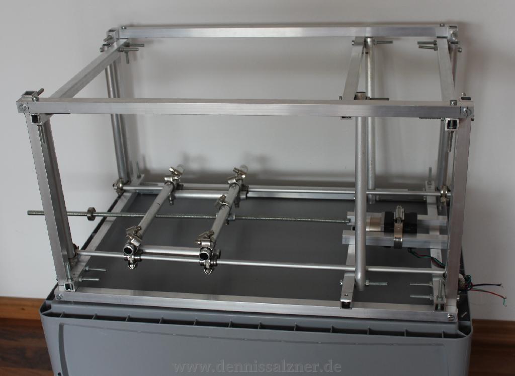
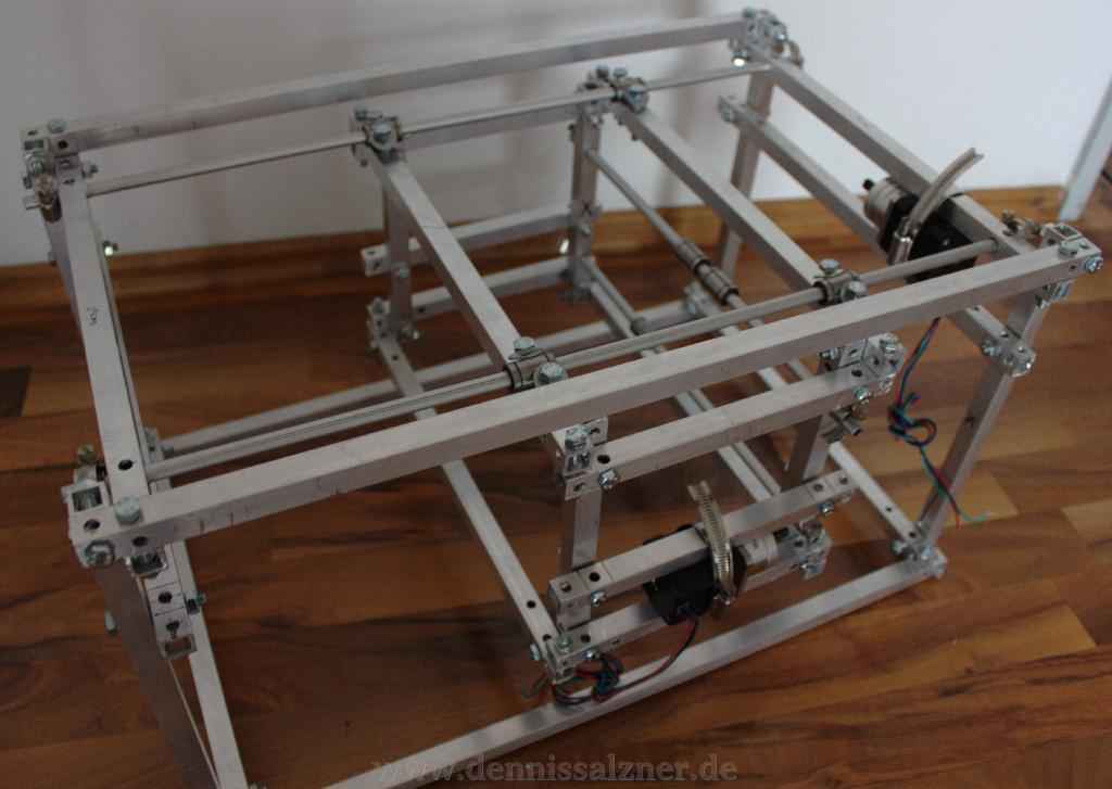
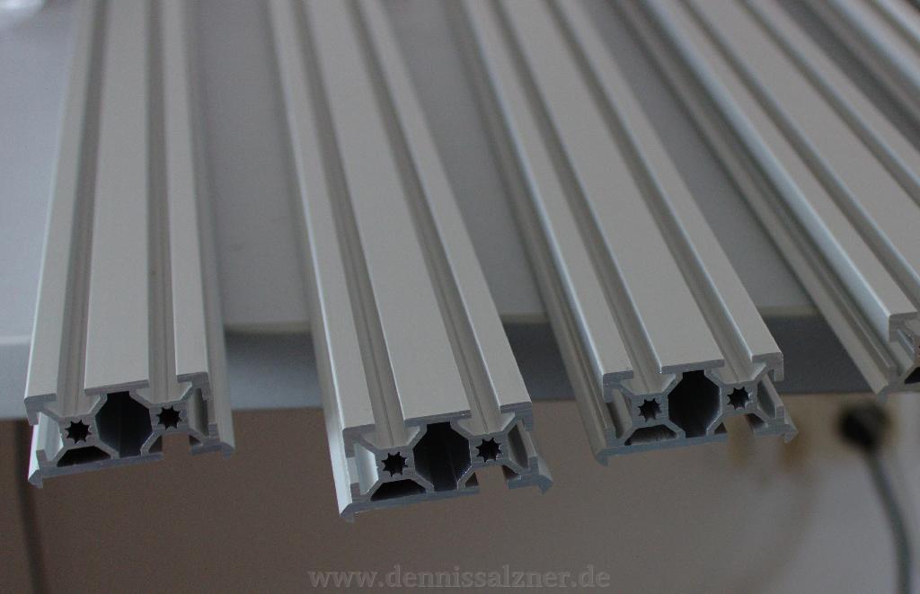
The build did work, but it wasn’t as sturdy, as I had hoped. A better solution may have been to use aluminium profiles that I didn’t even know existed at the time. They are more expensive, but allow builing accurate 90 degree angles easily. They can also be taken appart and recombined later, if the design does not work out.
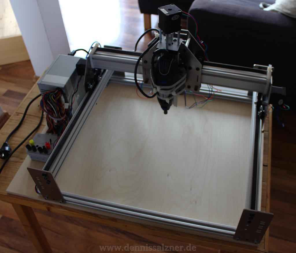
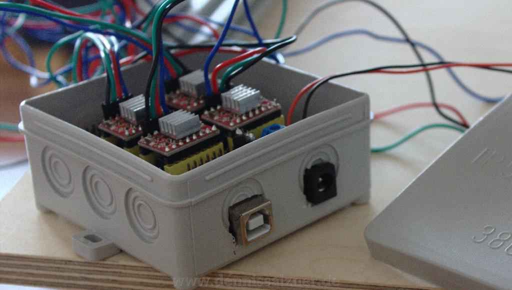
After some reasearch I found “MakerSlides” which are a special type of aluminium profiles with a lip for a wheel and ball bearing to travel on. From there I found CNC milling kits that use aluminium profiles and are belt driven. They had become available and affordable in the meantime. I decided to give up on constructing my own mechanics and went with the mechanics kit from a ShapeOko 2. Setting up the mechanics kit was a bit of a challenge, as the german supplier hat to adapt most parts from imperial to metric sizes, but it only took an evening or two. I ordered the suggested high quality motors seperately and for the electronics I found an Arduino motor driver base board with small poststamp sized stepper motor drivers that are stuck on the baseboard. Firmware for the Arduino was found online and with it the “grbl” G-Codes (positional commands) can be sent to the CNC mill from the computer. Tools like the “Universal GCode Sender” can then send the G-Code to the CNC mill from file. For my first designs I used SketchUp and an export plug-in to Inkscape. From Inkscape G-Code can be exported via another plug-in.
This solution meant having to ditch my previous designs and it did require some modifications, but it was far easier to set up.
How
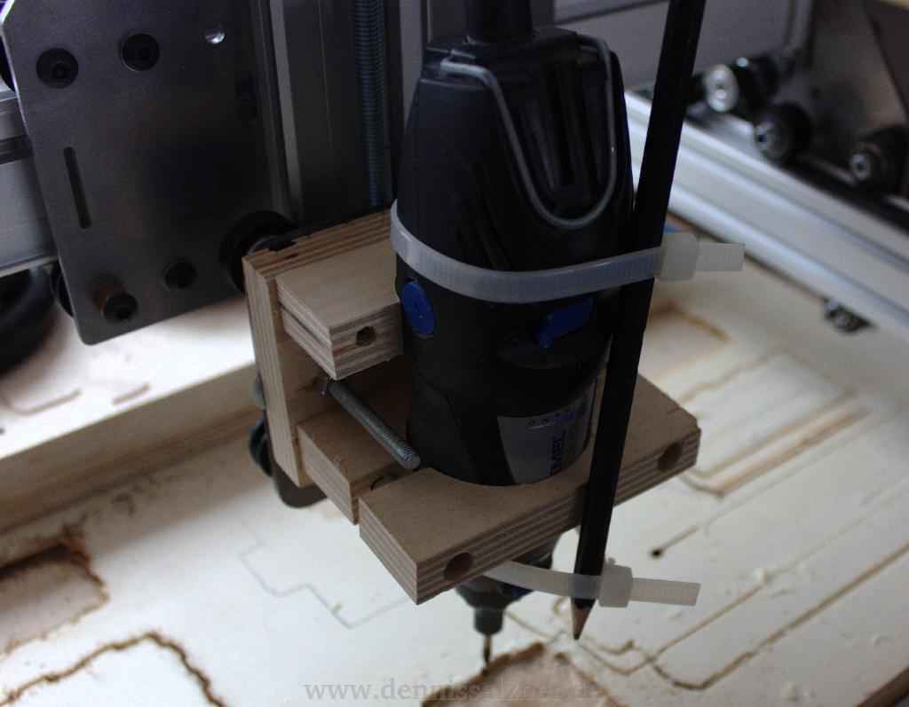
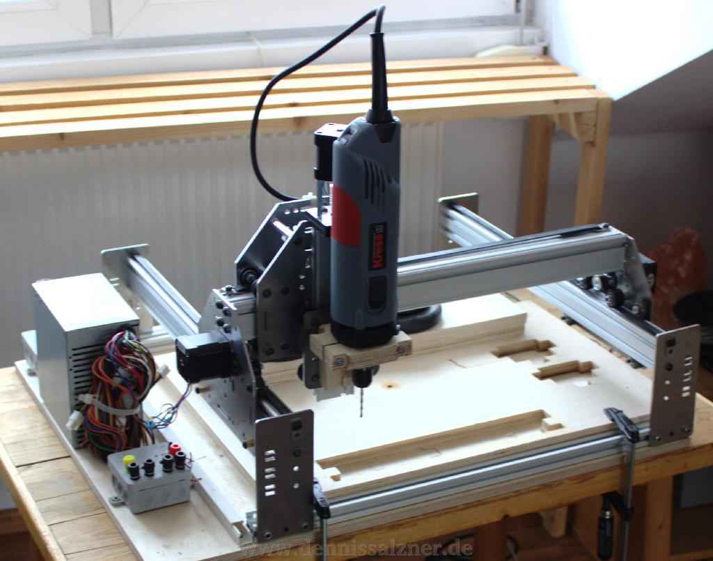
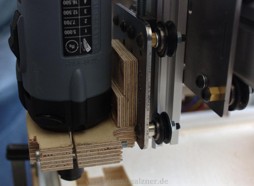
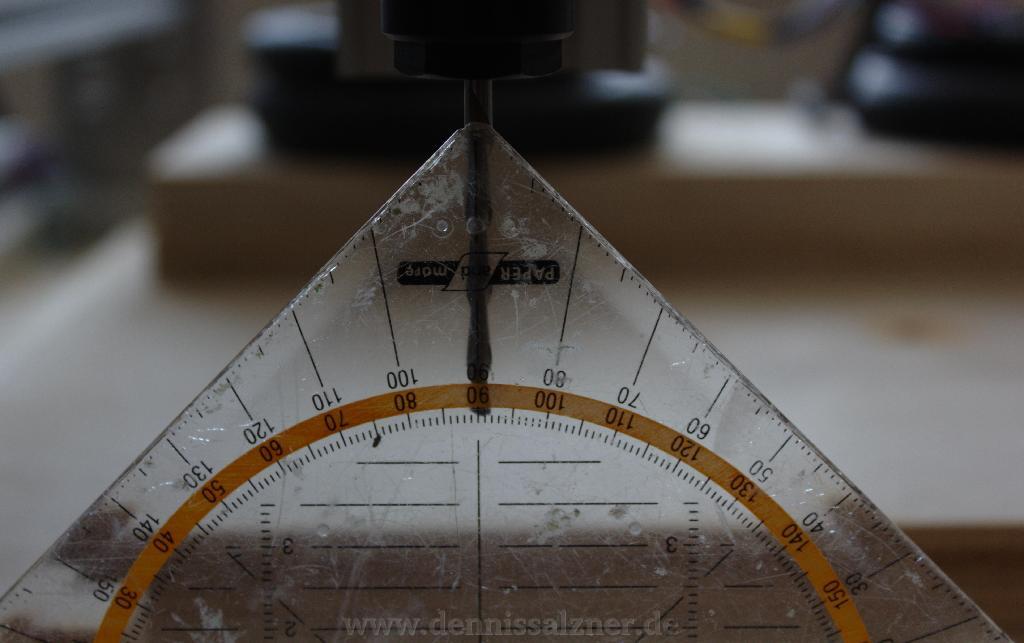
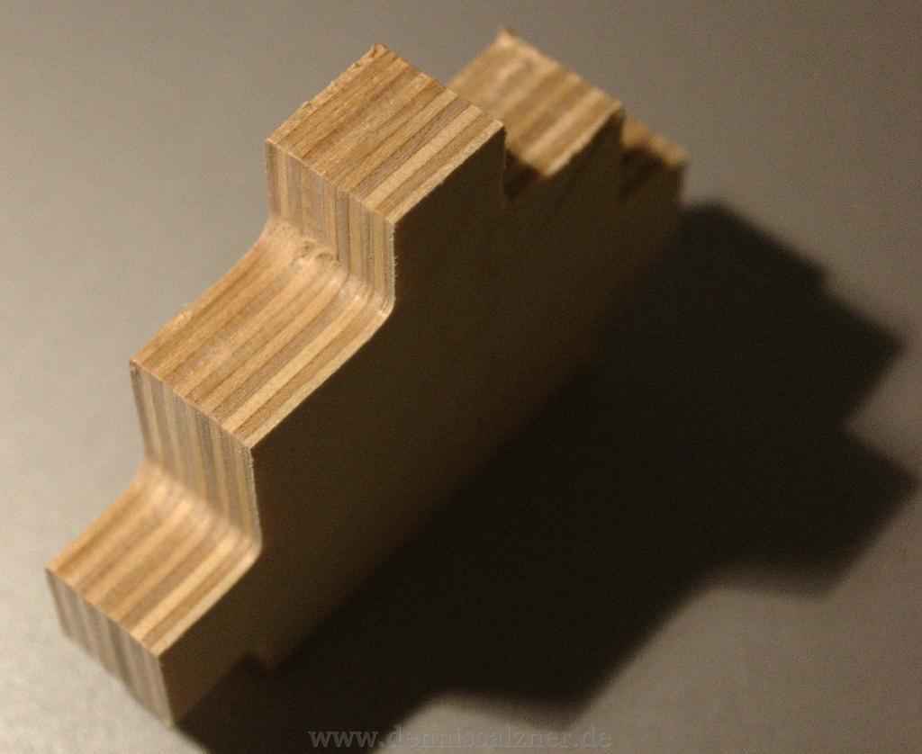
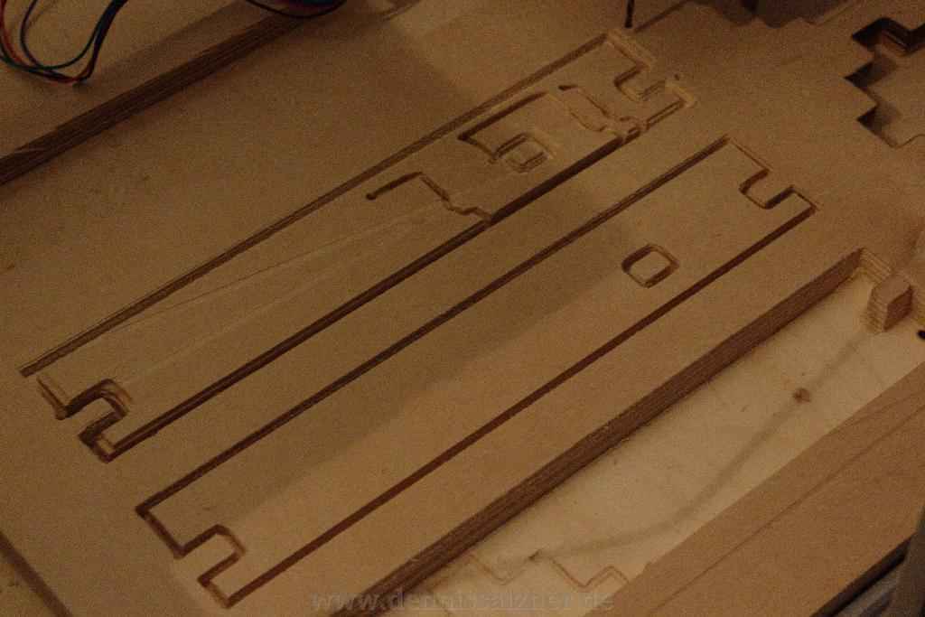
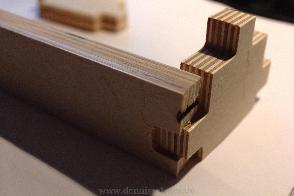
For the ShapeOko build I use the same computer ATX power supply as before, with the Arduino stepper motor board and drivers. As a rotary tool I used my standard Dremel at first, but quickly realized that it was not powerful enough and the spindle was not accurate enough for CNC milling. I switched to a professional Kress 1050 rotary cutting tool that costs almost as much as the entire mechanics kit. I needed a custom mount for the cutting tool, but was able to manufacture my own from wood with a very reasonable preceision.
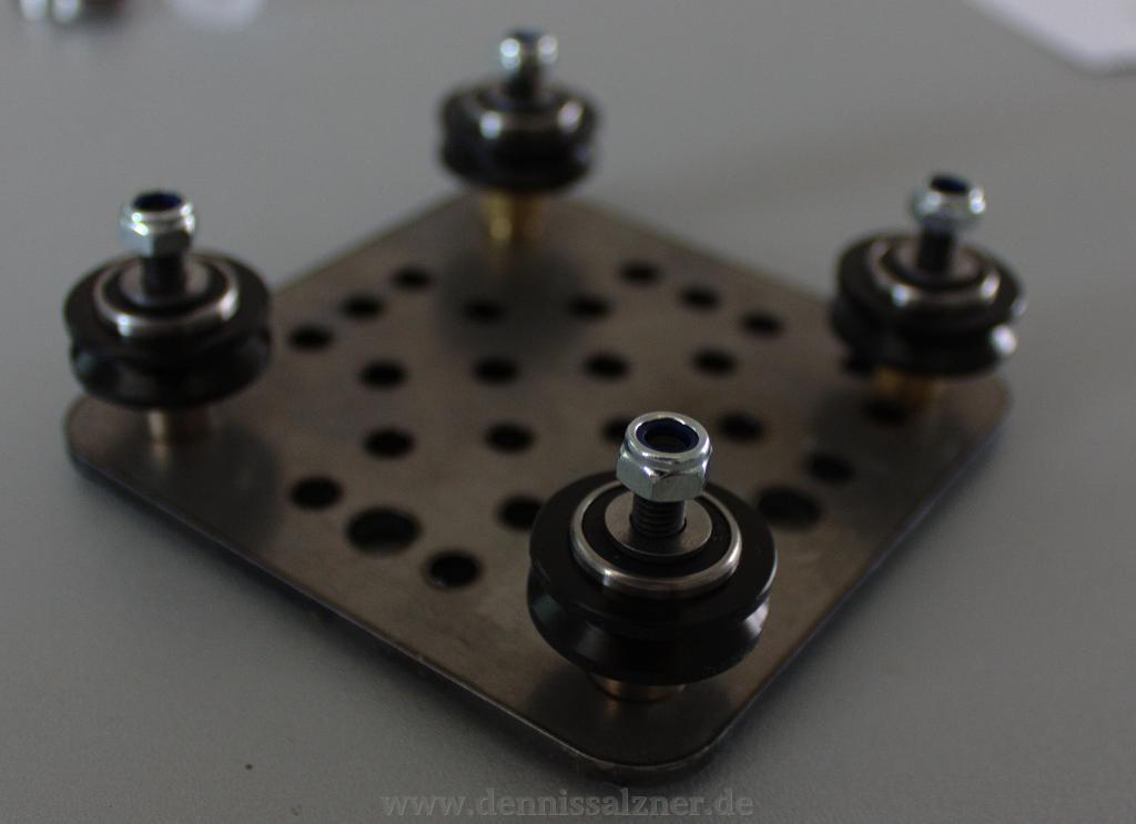
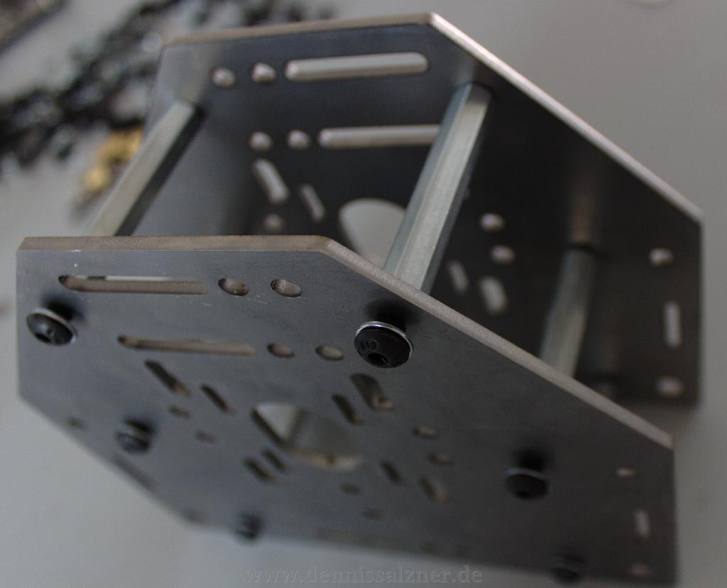
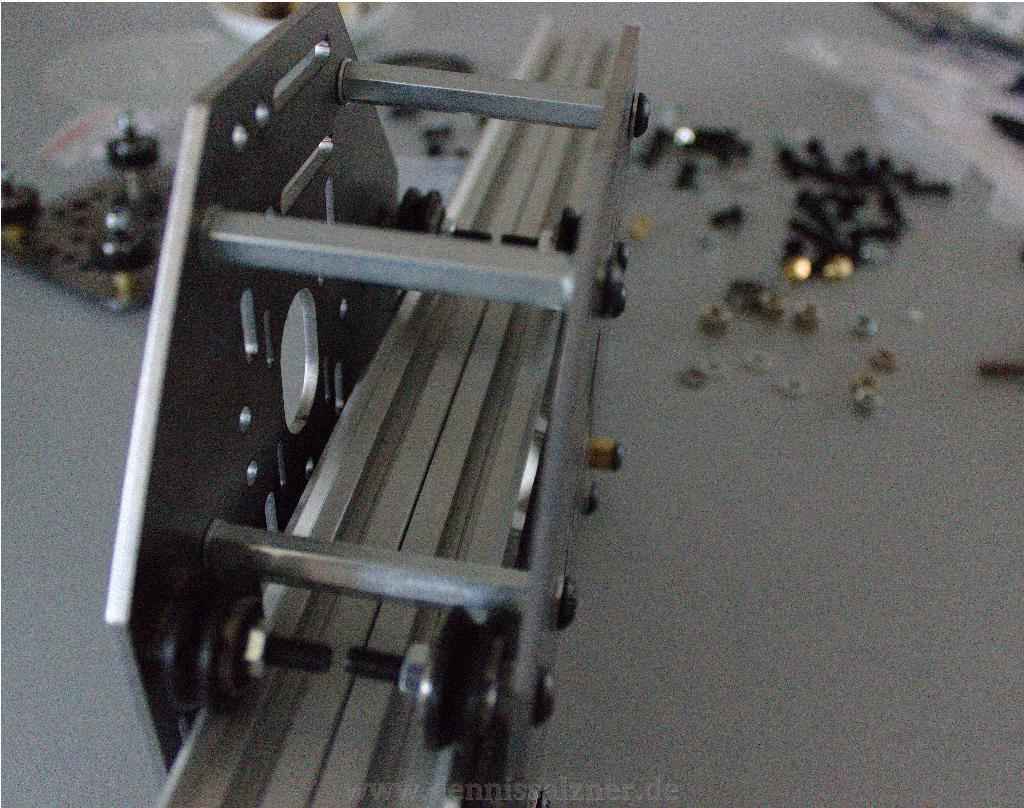
The construction of the ShapeOko is fairly straight forward using the provided online manual. The kit uses the aforementioned makerslides, a type of aluminium profile with an additional lip for a ball bearing and wheel to travel. The bulk of the work is in putting together the various carrages for each of the axis.
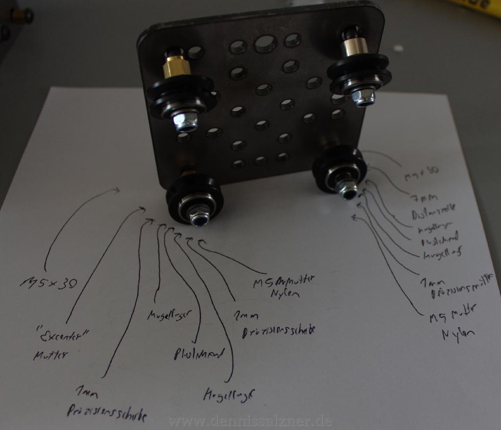
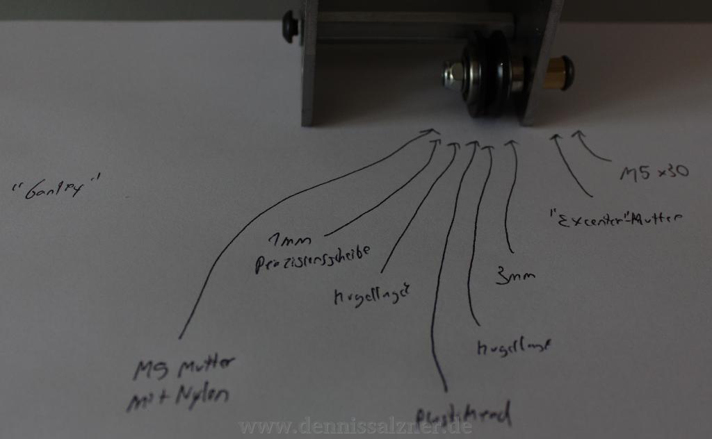
There are a lot of nuts and bolts involved and the adaption to metric parts from imperial parts in the original design for my european kit meant I had to get creative in order to get the positioning of these ball bearings and wheels right.
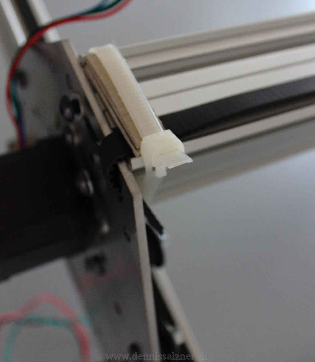
Some clamps for attaching the belts were missing, so I used zip ties as a start and later moved to paperclips that I bent around the teeth of the belts. This works fine and is how I have the belts attached to date.
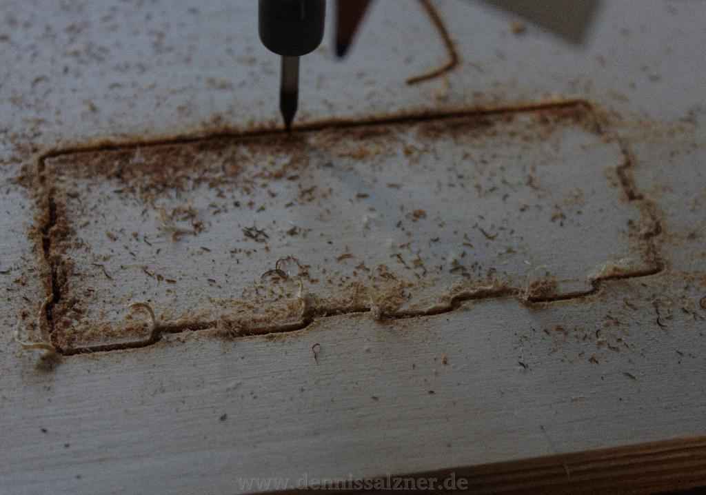
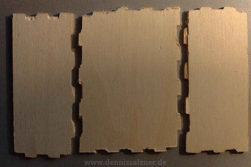
The first results after an evening or two of constructing were very promising. From there I started tweaking the machine and software parameters and tested it with various materials.
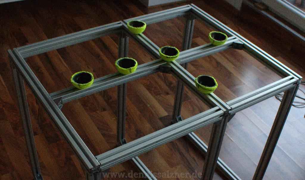
Vibrations and noise are a big issue. It is difficult to use the mill in an appartment during late evenings. I found that a frame with halved tennis balls underneath the machine can significantly dampen the vibrations from the mill.
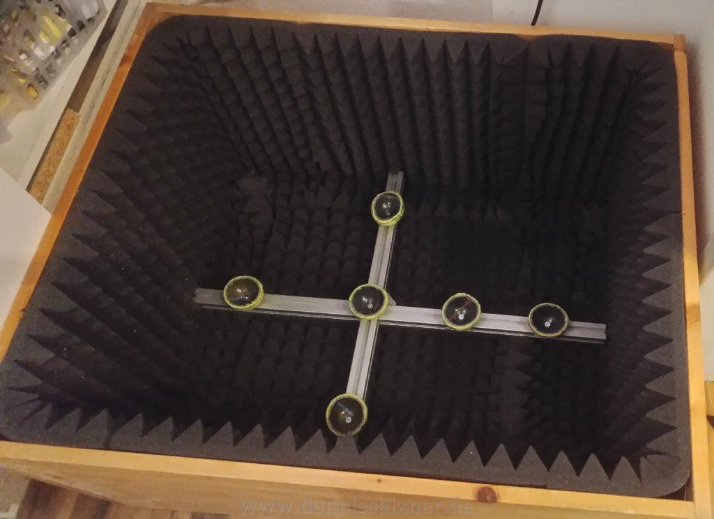
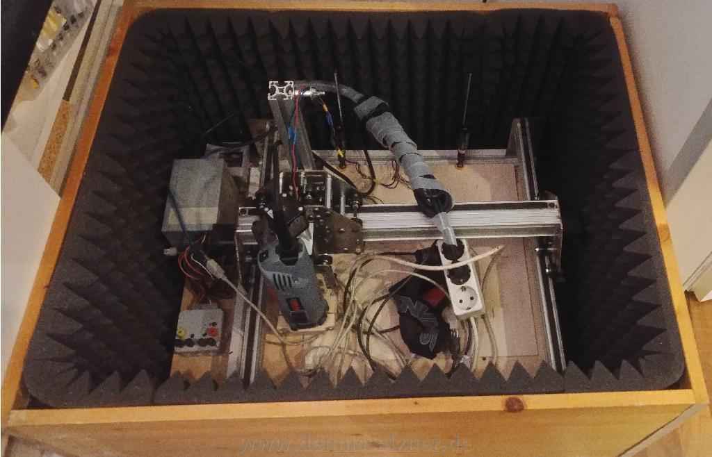
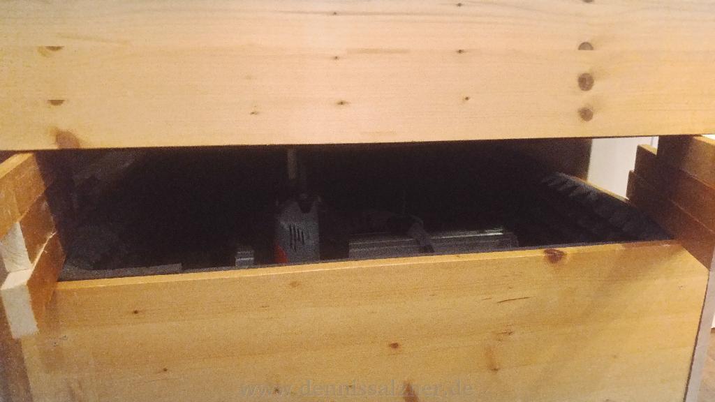
From there I then took matters even further and built a noise dampening box with a lid. This is of course a potential fire hazard, but a CNC mill should never run unattended in either way. The risk of material coming loose and having the mill grind along the material in a single spot causing a lot of excess heat and a potential fire is far to great.
Progress
The machine works very well and reliably though I don’t have much spare time to use it often. A major inconvenience to such machines is the lack of well functioning software. When I started I had my workflow figured out: I would use “SketchUp” to create the 3D design, lay all the pieces flat afterwards and export the 2D view of pieces to cut to “Inkscape” via the “SVG Exporter” Plug-In. In “Inkscape”, a vector drawing programm, I could export the milling machine commands, the G-Code, to a file using another plug-in. The file could then be played back on the machine using the “Universal GCode Sender”. None of the mentioned applications and required plug-ins were particularly stable. A while ago, while reinstalling my computer, I noticed, that “SketchUp” is not available as a standalone application anymore. The company behind it has switched to a cloud service. This means fiddling with the 3D models in a browser and the export plug-in to “Inkscape” can’t be used anymore either. I went back to 2D design in “Inkscape” and while “Inkscape” is a good program and the open-source community has done an excellent job in tackling such huge software, it does crash ever so often. Nevertheless I have used the CNC mill for countless projects and I’m always excited to see the precision and results that I could have never achieved by hand.