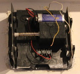
Fig.1: Unmodified doorbell
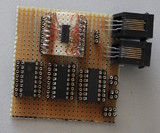
Fig.2: Stripe board circuit without wires
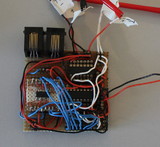
Fig.3: Stripe board circuit with wiring
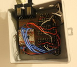
Fig.4: In a junction box - relay version.
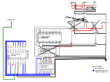
Fig.5: Schematic
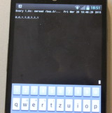
Fig.6: Reading the counter with a cell phone
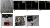
Fig.7 Redesign
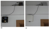
Fig.8 Final result
1-Wire Doorbell and Internet
What?
My doorbell doesn't work properly. So I set out to fix it. But then I realized I couldn't do so easily. The reason is a faulty switch outside of my appartment. I can't repair it, because there is mains current running through another switch next to it. I can't shut that off, because the fuse is located somewhere in the building and I don't know where. But I had to do something. After all I had set out to "fix" something. So I decided to connect my doorbell to the internet.
When?
I was sitting here the other day trying to study. Got bored. Thought about ordering pizza. But damn - the doorbell doesn't work. Opened it up. Realized I couldn't do much as of now. But then...
Why?
People usually notice the disfunctional bell. They can hear that it's not rining. Then they decide to knock - or they wait even longer. But nobody likes to wait... they do knock. But then they ask me why I haven't fixed it. It's becoming a running gag with my friends.
Background?
My doorbell is a very simple device: There is a 9V battery and a solenoid which hits a metal plate on rubber hinges that creates the sound (Fig.1). The switch outside functions as - you guessed it - a switch. It closes the circuit thereby connecting the battery with the solenoid, which triggers it.
How?
So how can I connect the thing to the internet? I have a One-Wire Bus running through parts of my appartment and, fortunatly, near the entrance door. A One-Wire Bus consists of a master device. This master device controls slave devices, which are daisy-chained along one long cable. This cable is connected to the master device. Slave devices can be anything from analog/digital inputs or outputs to temperature sensors. The master can read the values of the slaves and feed them into a computer. Each slave has a unique id by which it can be addressed.
The big advantage of the One-Wire Bus over say the CAN or RS485 are readily available components. There is no need for microcontrollers and all the work that goes into programming them. Most slave devices are also parasitic - which means they get by using power only from the bus data lines. This makes external power supplies or batteries for the slaves unnecessary.
A disadvantage is that 1-Wire only allows one master on each bus. The trouble with this is that sensors cannot speak on the bus without being asked to do so by the master. What this means is that sensors have to be actively polled in order to catch changes. Push buttons for example would need to be held down until the Master polls and registers the new state. Short changes can easily be missed.
But what I can do is use counter IC's. A counter keeps track of how often a button was pressed and it can react to fast changes as well. The master will be able to register the changes even if it missed the event by looking at the state of the counter later on.
The company that produces 1-Wire devices used to sell the DS2423 - a 4kBit Counter IC which acts as a slave device. But they've discontinued it.
What I do now is connect a DS2408 8 Bit input/output slave device to a 74HC590 Counter-IC. Then I put a HEF40106B Schmitt-Trigger in front in order to debang the switch. Otherwise one button press could be registered as multiple presses.
This solution proved to work fairly well. I've used this to monitor energy meters and my gas meter (well the later didn't work that well, but that's another story). Now I'm connecting it to my doorbell.
What does all this mean? The 1-Wire Master can poll the slave for the state of its 8-Bit I/O Pins. The answer is the state of the counter IC connected to it. The master is hooked to a linux server, which can use this information and do whatever I tell it to do. So if the counter state changes - I tell it to E-Mail me. And the counter IC increments each time someone rings the bell. So there you have it: Doorbell connected ot the internet.
Progress?
I've decided to solder directly onto a stripe board. Connecting the SMD type 1-Wire Chip was a pain, but it was still a lot quicker than designing and etching a PCB. What I do nowadays is use many socket strips (Fig.2). That way I can jumper around wires anywhere I need them (Fig.3). It doesn't look nice, but it works. And wires don't come loose - usually.
And this was a very wise choice as I realized I had to make some changes later on.
My first design used an ULN2003A Darlington Transistor-Array. The idea was to have the switch trigger the counter-IC and the input of the ULN2003A. The output of the ULN2003A would run the 9 Volt for the bell.
But this proved stupid: If the 5V line of the 1-Wire Bus would have been cut, the ULN2003A would shut off and the doorbell wouldn't work anymore. I also had a practical issue with this: It would mean running 2 wires for the battery power, 2 additional wires for the bell and 2 more wires for the switch - all going to my contraption.
It turned out to be far more fail-safe and convenient to use a simple relay. This also isolates the circuits from each other. The relay is now hooked up directly to the doorbell circuitry. And the other side, the side that closes as soon as current is applied, is connected to the counter IC and to 5V logic power. The result is a much simpler circuit (Fig.4)
The only remaining issue is that the solenoid causes fluctuations and these fluctuations cause the relay to switch back and forth. But as long as it doesn't do this exactly 255 times (this would overflow the counter and bring it back to the value it had before) - it's all good.
The final schematic is a mess, but it works for me (Fig.5).
And debugging and testing is fairly easy: I've connected my cell phone to my server via SSH (Fig.6). And then I ask the Linux library for 1-Wire (owfs) what the state of the counter is. Using "watch -n1 ..." in order to automatically refresh. That way I can ring my own bell, standing outside, while driving my neighbours insane and see if my server notices any of this, on my phone. And the whole thing doesn't look that bad - at least by my standards (Fig.8).
Oh and there's a 10k pull-up on the counter line...
Update 2015-03-21-Sa - Redesign 3:
I didn't like the oscillating relay. My first plan was to add a lowpass filter. Something to reduce the fluctuations to one clean peak. The circuitry in the bell is simplistic (Fig. 7a). Measuring the signals between battery and switch with an oszilloscope showed the oscillation (Fig. 7b). The fluctuations vary in voltage from -46V to 73V (Fig. 7c). I hadn't expected it to be that bad.
So I added a diode (1N4004) to remove current running back from the coil of the bell to the circuit. The result looked a lot better (Fig. 7d). All we see now is the switch toggling and the negative current. The rest is filtered out.
I thought I could run the relay off of this. That worked, but only when the bell wasn't connected. I assumed this was due to the small resistance in the coil of the bell. The same circuit would drive either the bell or the relay depending on whether the wire to the bell was connected.
Then I tried to bring the resistance of the coil up to the level of the relay, but then the coil would hardly function (Fig. 7e). I decided to bring in transistors to drive the bell. A PNP, because the bell is wired to the negative lead of the battery and I needed to switch the positive lead. After that I opened up the rest of the bell (Fig. 7f), rewired it and used an NPN transistor. I needed a very low resistor, 75 Ohms, connected to the transistors base for this to work. But the same problem remained as before. I couldn't drive both the relay and the bell.
I still had the ULN2003A darlington transistor array, so I thought it would be a better choice and swapped the NPN transistor for it. But half way there I had a better idea: What about driving the bell with the relay instead of the counter. This is so stupidly obvious, but I was thinking in so many different ways I just didn't come up with that at first.
But then the relay was oscillating again. Then I finally figured out that the relay I was using was rated for 12V and the 7 to 8V coming from the battery were far too weak. So I hooked up a 5V relay and that worked.
The end result is a switch that connects to the counter through a schmitt-trigger. The switch also activates a relay. This relay connects the solenoid in the bell to the battery (Fig. 7g).
I didn't bother adding a transistor to drive the relay. The bell's original circuit near shorts out the battery every time someone hits the switch anyway. And the counter can handle the 9V - after all I was hitting it with 73V peak before.
The device is now fully working (Fig.8).
What can I do with this? I can receive e-mails notifying me when someone was at the door. That way I know if I've missed the parcel delivery service. And I can have it automatically mute or pause the music - my music playback software also runs on the server.
Update 2015-03-23-Mo - E-Mail Notify:
E-Mail notification was easy to set up (on my Linux server). All I needed was msmtp. I configured it to use my gmail account to send emails.
yum -y install msmtpIt had to be configured:
vim ~/.msmtprc
account default
host smtp.gmail.com
port 587
from [email address]
tls on
tls_starttls on
tls_trust_file /etc/ssl/certs/ca-bundle.crt
auth on
user [email address]
password [password]
logfile ~/.msmtp
And then I was receiving E-Mails by issuing:
echo -e "Subject: Hi\n\nTest" | msmtp [email address]I've written a short script in order to do this automatically when someone rings the bell:
1 2 3 4 5 6 7 8 | #!/bin/bash
ZNEU=`/usr/bin/owread /bus.0/[1-Wire IC Address]/sensed.BYTE 2> /dev/null`
ZALT=`cat /root/onewire/zaehler_klingel_wohnungstuer.txt`
echo $ZNEU > /root/onewire/zaehler_klingel_wohnungstuer.txt
if [ $ZALT -ne $ZNEU ]; then
echo -e "Subject: e350 Wohnungstuer\n\nEs hat geklinkelt" | /usr/bin/msmtp [E-Mail]
fi
|
All this does is check the counter. Overwrite the last seen value with the new one. Compare it to the last seen value. Send an E-Mail if they differ. One should make sure it is executable:
chmod +x /root/onewire/zaehler_klingel_wohnungstuer.sh
And add it to crontab to make it run periodically. I set it up to check the bell every minute:
crontab -e
*/1 * * * * /root/onewire/zaehler_klingel_wohnungstuer.sh
Now I receive E-Mails within a minute when someone rings the bell.